7-9 GPM Gallons per Minute- 27-36 LPM Liters per Minute at 35 PSI.
We acknowledge the original source of the concept behind these calculations:http://www.mcnallyinstitute.com/13-html/13-12.htm
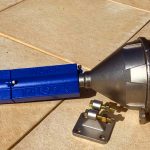
Note: THE IMPLODER- has a 1/2″ passage diameter hole thru the centers of the magnet array (down the long pipe), and it has an estimated ORIFICE EFFECTIVE DIAMETER (approximate- 5 little tubes come down and meet at a complex convergence) of 1/4 to 5/16″.
The IMPLODER uses an ABS Plastic in the nozzle for several reasons:
- injection molding compatibility
- food grade rating for water contact
- transparency to make the principle of The Imploder – Implosive Flow visible, attractive, and educational.
This material naturally while strong – does have limitations:
Re- Maximum Design Pressure:
The Imploder- was originally designed to be a discharge point spray for agricultural use
The magnet end is the discharge point- the nozzle end is the input point- because the water molecules need to have critical spin density upon entering the strong magnetic Z PINCH to inductively motorize the implosive effect- which centripetally enables the molecules to become molecularly stable as smaller clusters, and become molecularly aligned more coherently- both of which help create the desired added solubility and bioavailability effect. Reduced molecular cluster size is part of the mechanism of increased relative surface area available to reaction- one of the primary mechanisms of increased solubility, bioavailability and also – increased reaction efficiency – in other applications LIKE COMBUSTION EFFICIENCY.
As such- for this application – (agricultural spray discharge point) – The Imploder- was designed for what is nominal standard home plumbing systems- which is typically (pump switch on- off points)- of ON 25 PSI, OFF 40 PSI.
Using epoxy assembly around the O-Ring- The Imploder is technically rated up to 45 or possibly 50 PSI maximum.
SO- in our calculations below- we are going to calculate a flow rate- based on a pressure of 35 PSI.
There are several reasons you might also benefit from installing a restrictive device, or orifice (like the imploder) in a piping system.
To create a false head for a centrifugal pump, allowing you to run the pump close to its BEP.
To increase the line pressure.
To decrease the flow through a line.
To increase the fluid velocity in a line.
The equation for flow through an orifice is a simple one to understand. Only the units are somewhat awkward.
Q = AV
Q = The flow in cubic feet per second (ft3/sec).
A = The area of the orifice in square feet (ft2).
V = The velocity of the liquid in feet per second (ft/sec).
Experience shows that the actual flow is quite different than calculated because of the different shapes of the various orifices. Look at the following diagrams and you will see some of these popular shapes. Each has been assigned a “K” value.
We will enter that “K” value into our equation and the new equation becomes:
Q = AVK
To make the equation easier to handle we can express the velocity “V” as:
![]()
g = 32.2 ft/sec2
h = Head across the orifice. If the downstream side of the orifice is pressurized use the differential head across the orifice.
If you do not know how to convert pressure to head, use this formula:
![]()
NOTE – if we set the PSI – here to 35 PSI – recommended for Imploder
– and note that At 4°C pure water has a specific gravity of 1. ( Some reference the s.g. base temperature as 60F.)
Then- for our 35 PSI Imploder recommended average pressure- we have Head (H) value of approximate 80.
It would also make sense to convert some of the terms in our equation to terms that are more convenient to use. As an example:
“Q” can be converted from cubic feet per second to gallons per minute:
1 ft3/sec = 448.8 gpm.
“A” The area in square feet can be converted to square inches:
1 ft2 = 144 square inches
Putting all of this together gives us a new formula that looks like this:
![]()

Let’s plug in some numbers and calculate a flow through a typical orifice.
Given:
h = 20 feet
A = 0.049 square inches
K = 0.62
Q = 25 x 0.049 x 0.62 x 4.47 or
Q = 3.40 gallons per minute
If we want to solve for the orifice area:
![]()
If you are uncomfortable working with the orifice area in square inches you can use the diameter instead. Use the following equation:
![]()
Inserting the 0.049 square inches we calculated from the prior formula we get
![]() or 1/4 inch
or 1/4 inch
We made our formula more user friendly by substituting some conversions and now we can make our calculations in gallons per minute and square inches, but the formulas would be better if we could measure the orifice diameter rather than the orifice area
I took you through this exercise to show you how the formulas we use in these papers are derived. We will re-write the flow and orifice diameter formulas again and maybe this time they will be simple enough for anybody to use. We will start with the flow formula and then fix the orifice formula:
![]()
The formula for calculating the orifice diameter becomes:
Let’s see if the formulas still work. Here are the numbers:
d = .250 or 1/4 inch
K = 0.620
Q = 3.4 gallons per minute
h = 20 feet – note this was the original HEAD we will show also the calculation with h HEAD = 80 for our 35psi.
We will begin by solving for flow (Q)
Here is the original Calculation for Head =20
![]()
Now we redo this for Head = 80 ( about 35 PSI):
Square root of 80= 8.94
Square root of 20= 4.47
So Our flow rate with our new pressure of 35 PSI, Head= 80 Instead of the Original Example Equation for Head = 20
Is almost exactly DOUBLE.
So: the Imploder for 1/4 Inch effective orifice would be 6.92 GPM – Gallon Per Minute- with 5/16 effective orifice that could be up to 9 GPM.
To convert GPM Gallons Per Minute to LPM – Liters per Minute: Multiply by: 3.785
So- 7 to 9 GPM becomes: approximately 27 to 36 LPM Liters Per Minute.
(Note below that could increase slightly based on the ratio of the orifice restriction point to the magnet bore diameter)
Orifice size:
![]()
All of these above numbers were generated assuming that you were moving water through the orifice. If you are making calculations for a liquid other than water you will have to factor in the viscosity of that liquid compared to water.
We also made an assumption that the orifice diameter is not greater than 30% of the pipe diameter. There is another formula we use for a less restrictive orifice.
Any time the ratio of the orifice diameter to the pipe diameter is greater than 30%
(0.30) you should modify the formula. The modifier (M) looks like this:

d1 = orifice diameter
d2 = pipe diameter
When you are using the modifier, the formulas look like this:
Now we will see what happens when a 0.250 inch (1/4) orifice is put into a smaller cross section 0.500 inch (1/2) pipe, ( 1/2″ IS OUR MAGNET BORE DIAMETER) – assuming the other numbers stay the same:

This means that you would have to multiply by 1.03 so the 3.46 gpm we got in the last calculation would become 3.56 gpm.
THAT WOULD BE ABOUT 7 GPM – WITH THE 80 HEAD/ 35 PSI.
How accurate are these predicted numbers? Anytime you make a calculation using flow as a as part of the equation, you will run into some variables that will affect your results:
The roughness of the piping inside walls affects the friction losses.
The piping material and allowable wall thickness tolerances.
Solids buildup inside the piping. Calcium in water applications and coke in hot oil applications are typical. Higher temperature usually hastens the solids buildup.